The requirement for increased capacities, higher material lift and increased conveying distances in “mass mining projects” has resulted in various belt conveyor developments.
An increase in drive size and belt strength is one option to address this requirement. Other options are alternative drive concepts such as driven idlers, TT-drives or tripper-booster drives. Unfortunately, it is not always possible to implement such alternative drive technologies and the traditional arrangement with head- and tail drives is often still the best technical and economical option. As such, this paper is focused on the standard drive arrangement.
Conveyor belts with a strength of up to 7 800N/mm have been in use for the last 20 years. Electromechanical drives, consisting of electrical motors (wound rotor or squirrel cage motor) and bevel helical gears with a capacity of up to 3 150kW, are currently in use in South American copper mines.
As described above, there are increased performance requirements
for belt conveyors today. Moreover, there are two possibilities to overcome this challenge:
• Reduced conveyor flight lengths
• Further increase in belt strength and drive size
Sometimes, the increase in the number of flights is the most economical way to achieve this, especially with regard to capex. However, if the conveyor routing does not allow additional transfer points, the main components – such as belt quality and drive size – are objectives for further development.
One such example is tunnel conveyors in which underground drive- and transfer stations are to be avoided or minimised due to the immense efforts required for excavation and for cooling of the drive components.
How then is one able to increase the installed power? Electro mechanical drives are limited by the capability of the bevel helical gear to 3500kW. Parallel shaft drive arrangements have increased space requirements and face limitations with flexible low speed couplings.
Gearless conveyor drives, acclaimed for their widespread use in mining hoists, are a suitable solution. Drive power of up to 10 000kW, per motor, is possible. There are no mechanical gears with the resultant advantage of higher drive efficiency and reduced efforts for maintenance. These
important advantages result in an interesting opportunity to employ gearless conveyor drives even in power ranges that have always been the realm of electro-mechanical drives.
Concepts for Gearless Conveyor drives
The idea of connecting a synchronous motor direct (without gearbox) to a drive pulley is not completely new. More than 30 years ago, the German company O&K installed two 3 100kW synchronous motors on a 3.7km long inclined underground conveyor at a German coal mine together with Siemens.
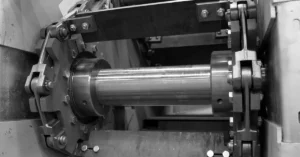
Synchronous motors operate across various industries and applications. Figure 1 shows a typical component arrangement on a mining hoist.
The same concept is applicable to belt conveyors. A motor, operating with pulley speed, is coupled directly to the drive pulley (figure 2). In combination with newly developed hightension belting (St 10,000) each drive pulley can transfer a drive torque of up to 1 800 000Nm (10,000 kW at 53rpm).
Gearless conveyor drive design
For gearless conveyor drives, synchronous motors with permanent excitation (with permanent magnets) or with external excitation (flow of electrical current through the exciter winding into the rotor) are possible.
Permanent magnet motors are suitable for medium power range applications, whilst externally excited motors are employed at the upper end of installed motor power applications. Figure 3 represents a
diagram of the motor types and the possibilities for motor arrangement.
Maximising motor speed is an important general principal for conveyors with gearless drives. Drive size and costs are directly influenced by motor torque since there is no gear between the pulley and the drive. An example: if it were possible to increase drive pulley speed from 50rpm up to 70rpm, motor torque and motor size would decrease from 765kN•m to 545kN•m with resultant significant cost savings.
Motor speed/rpm is defined by:
• Belt speed
• Drive pulley diameter
If it were possible to increase belt speed from 5.2 m/s up to 6.6m/s and to decrease drive pulley diameter from 2.0m down to 1.8m, the aim, as described above, would be reached.
Belt speeds up to 7m/s are common for overland conveyors.
In the event of higher belt speeds, the idler concentricity and the idler speed would have to be double-checked. Machined and balanced idlers might be required to limit transversal belt oscillations and to increase idler lifetime in the event of higher belt speed values. Larger idler diameters are the other option. With limited idler speed (about 750rpm) standard
idlers will meet the requirements as well.
The forces between pulley and belt, as well as belt quality, define drive pulley diameter. Pulley face pressure has an influence on the friction factor between pulley and belt. Furthermore, limits in pulley face pressure and pulley shear pressure must be taken into account for pulley lagging selection.
The pressure under each cord of the belt carcass must be considered to
avoid cutting the cord into the belt cover. Steel cord diameter of the
belt carcass defines the minimum belt-bending radius considering belt
splice characteristics.
Actual DIN and ISO standards provide data tables for pulley diameter
selection based on belt type, carcass/cord thickness and belt tension
values. This design method is sufficient for standard belt conveyors.
However, for conveyors with “high-powered gearless drives” it would be more beneficial to also consider some of the details for drive pulley diameter selection as described above.
Permanent magnet motors
Permanent magnet motors have been around for decades – in ship propulsion, pumps, fans, blowers, wind power generators, automotive, etc.
For conveyor drives, there are two different drive systems available on the market:
• Permanent magnet motor with planetary gear
• Permanent magnet motor directly coupled to the drive pulley
As the focus of this paper is on “high powered gearless drives”, the planetary gear system is not considered further.
Compared to an externally excited synchronous machine, a permanent magnet motor is lighter, more compact and more energy efficient since there are no losses for external excitation.
There are two possibilities for motor installation:
• Rigid coupling between rotor and pulley (flange coupling)
and torque arm between stator and steel structure or
foundation (left hand side on figure 5)
• Base mounted motor and torsional rigid coupling between
rotor shaft and pulley (right hand side on figure 5)
Externally excited motor
Externally excited synchronous motors are state-of-the-art motors specifically suited for large equipment pieces such as large compressors, grinding mills, grinders and mining hoists.
The motor consists of the components shown in figure 6.
For motor installation, there are two possibilities:
• Motor with bearing(s) (flexible coupling between drivepulley shaft and motor shaft)
• Bearingless motor – cantilevered design (rotor direct coupled to the drive-pulley shaft)
Both systems boast advantages and disadvantages. A main advantage of a motor with bearings is that the drive can be assembled in a clean motor-factory environment. The motor is then shipped to site after factory testing in one unit without requiring disassembly for installation. In the event of motor failure, it is possible to disconnect the drive in a short time.
It is important that the air gap between stator and rotor (up to 20 mm) remains constant and motor bearings are helpful in order to minimise air gap variations, caused by the pulley
shaft bending with different belt tensions, all factors that work towards improving motor efficiency.
For smaller power ranges (2.5 and 3.5 MW), a motor with bearings on both sides and a geared coupling between pulley and motor is a usual configuration. At upper power ranges, a support bearing on the non-driven motor end and a membrane coupling between rotor shaft and pulley is employed as a Takraf patented solution.
The advantage of a direct-coupled rotor solution is the simplicity of the system. A special drive pulley that promotes reduced bending of the shaft is required to keep the air gap variation within an allowable range.
On both motor installation types, the stator can be directly connected to a foundation or to a steel structure.
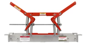
As a patented solution, with a special motor frame design, the drive (the stator) is easily adjusted with spindles, hydraulic cylinders and/or eccentrics on the steel structure. In case of pulley re-alignment requirements, the related drive adjustment can be conducted without significant effort.
Motor design selection, in conjunction with the entire “drivetrain” (incl. drive pulley etc.), is only defined after discussions with the client and follows on from project specifics, such as surface or underground operation and so on.
High-powered gearless drive conveyor example Takraf has installed eleven externally excited synchronous motors with 900 kNm (5 000kW at 53rpm) each on the Chuquicamata Underground Project conveyor system in
Chile. Design capacity of the system is 11 000 t/h of primary crushed copper ore.
There are three conveyors boasting high-powered gearless drives as can be
seen to the left.
All conveyors boast head drives only. There are two 5 000kW motors at the primary drive pulleys. Both principal conveyors boast two 5 000kW motors
at the secondary drive pulleys as well.
The secondary head drive pulley on the overland conveyor boasts one drive.
To reach the maximum possible motor speed, which results in minimum motor torque, was one of the key design tasks.
A belt speed of 7m/s, in combination with optimised material transfer points, enables safe and efficient conveyor operation.
Idler concentricity and dynamic idler balancing values are specified with tight tolerances. It was therefore possible to reach these specified values without machining the idler’s surface.
The material transfer points are designed in order to protect the conveyor belt from the direct impact of larger lumps, to reduce belt wear by means of smooth material loading and to increase maintainability of all components. The combination of rock-box design and grizzly finger arrangement
was simulated by Takraf employing DEM-Analysis, prior to finalising the design.
After the belt speed was set, the minimum possible drive pulley diameter had to be selected. The minimisation of drive pulley diameter for high-powered gearless drives is a general approach.
Due to the fact that the drive station of the principal conveyor C-01 is located underground in a cavern, it was required to minimise the number of pulleys and pulley diameters.
The influencing factors for drive pulley selection are:
• Pressure under each cord of the belt carcass and minimum belt bending radius considering belt splice characteristics
• Pulley face pressure and pulley shear pressure
• Friction factor between pulley and belt
A three-pulley drive station layout (primary drive pulley, secondary drive pulley and bend pulley) was the preferred option driven by the space limitations within the underground cavern.
1 – Pressure under each cord of the belt carcass
As per conveyor calculations, the belt tensions in operation
with design capacity at the primary drive pulley are T1=3 600kN on the tensioned side and T2=2,300kN on the slack side. Belt tension on the slack
side of the secondary drive pulley is T3=1 000kN. With the steel cord diameter and the cord pitch of St 10 000, the minimum drive pulley
diameter is 2 400mm with an allowable pressure value of 2.0 MPa under each cord.
With an additional traversal reinforcement (breaker) under the cords, it would be possible to increase allowable pressure values slightly.
2 – Pulley face pressure and pulley shear pressure
New extents in belt strength (St 10 000) led to challenges in pulley lagging design. Face pressure values up to 1.2 MPa are known from literature,
whilst maximum published shear pressure is 0.15 MPa.
Both values are valid for hot vulcanised rubber lagging.
A drive pulley diameter of 3 000mm would thus be required with the values above.
The possibility of allowing for increased pressure values was discussed with Rema Tip Top in Germany, the company that applies the pulley lagging. As a first decision, hot vulcanised rubber was selected as the best solution for this application.
With 1.5 MPa of face pressure and 0.6 MPa of shear pressure, new limits for actual rubber compounds were able to be achieved. Through the application of these new limits, it was possible to reduce the minimum drive pulley diameter to 2 500mm.
3 – Friction between pulley and belt
Criteria 1 and 2 led to a minimum 2 500mm drive pulley diameter. The related friction factor depends on the pulley face pressure and on the surroundings (dry, wet or dirty environment/mud between pulley and belt).
The average pulley face pressure in operation is:
• 1.35 MPa at the primary drive pulley and
• 0.75 MPa at the secondary drive pulley
Based on the belt tensions above. Diagram 1 shows, for a wet environment (at the underground cavern), the following:
• Friction factor μ=0.22 at the primary drive pulley and
• Friction factor μ=0.28 at the secondary drive pulley
With the belt tensions and friction factors, we are able to check required belt wrap angles 1 and 2.
The Eytelwein equation:
1
provides required wrap angles of 1 ≥ 117° at the primary drive pulley. The belt wrap angle, as designed, is 174°. With the selected parameters, this
angle is split in 117° active angle and 57° passive angle 2 ≥ 170° at the secondary drive pulley. The belt wrap angle, as designed, is 188°. With the selected parameters, this angle is split in 170° active angle and 18°
passive angle After double-checking the friction between pulley and belt, all three criteria were met with a 2 500 mm drive pulley diameter. This diameter was then employed for conveyor design and for motor torque specifications.
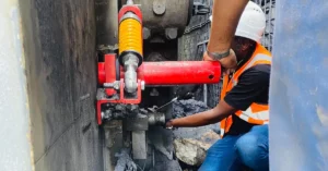
Figures 8 and 9 show the motor in the motor factory and during construction on site.
This paper was fi rst presented at the
Beltcon Conference in 2019.
Copyright is vested with IMHC. www.
beltcon.org.za
Takraf
Dr. Mario Dilefeld
E-mail: mario.dilefeld@tenova.com
Matthias Pohl
Email: matthias.pohl@tenova.com